


HOME > LINEAR BEARINGS > BALL BUSHINGS > BALL SCREW SPLINE SPBR
BALL SCREW SPLINE SPBR (TORQUE RESISTANT):
PDF Catalogue of Linear Bearings
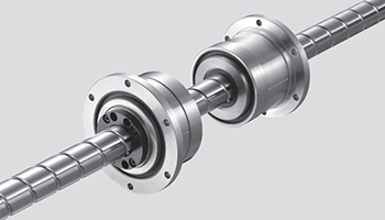 |
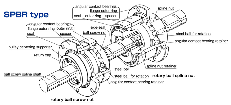
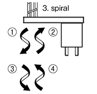
The Ball Screw Spline shaft has a screw thread and a spline groove. The SPBR module consists of a Rotary Ball Screw nut and a Rotary Ball Spline nut. The combination of the ball screw and ball spline on one shaft provides a system which allows independent linear and rotary motion, as well as spiral motion when the linear & rotary motions are combined. Typical applications are SCARA robots, assembly machines, loaders, tool changers etc For torque resistant applications where only linear motion is required, please see SPBF type. |
Rotary Ball Screw Nut:
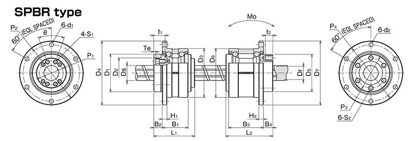
a) Dimensions (mm)
| Part Number | D1 (h7) |
D2 (H7) |
L1 | P1 | θ | S1 | f1 | Te | D3 (0 -7µm) |
D4 | H1 | B1 | B2 | P2 (PCD) |
d1 |
| SPBR16 | 40 (+0 -25µm) |
32 |
43.5 | 25 | 40º | M4 | 12 | 2 | 52 | 68 | 5 | 27.5 | 9 | 60 | 4.5 |
| SPBR20 | 50 (+0 -25µm) |
39 (+25 0µm) |
54 | 31 | 40º | M5 | 16 | 2 | 62 | 78 | 6 | 34 | 11 | 70 | 4.5 |
| SPBR25 | 58 (+0 -30µm) |
47 |
65 | 38 | 40º | M6 | 19 | 3 | 72 | 92 | 8 | 43 | 12.5 | 81 | 5.5 |
| Part Number | DS |
Lead | Dr |
| SPBR16 | 16 | 16 |
13.4 |
| SPBR20 | 20 | 20 | 17.2 |
| SPBR25 | 25 | 25 |
21.9 |
b) Loads
| Ball Screw | Angular Contact Bearing | Moment of Inertia | Mass | Ball Screw Nut | ||||||
| Load Ratings (kN) |
Load Ratings |
Nut |
Screw Shaft |
Nut |
Shaft |
(Based on Dm.N) | ||||
| Part Number | Ca |
C0a |
Car |
C0ar |
Max rpm | (kg.cm2) | (kg.cm2/mm) | (kg) | (kg/m) | Max rpm |
| SPBR16 | 4.62 | 8.59 | 11.1 | 22.2 | 4000 | 0.60 | 4.43x10⁻⁴ | 0.45 | 1.47 | 4,179 |
| SPBR20 | 5.77 | 12.2 | 14.4 | 30.5 | 3200 | 1.75 | 1.12x10⁻³ | 0.76 | 2.33 | 3,414 |
| SPBR25 | 8.62 | 19.2 | 18.2 | 39.8 | 2800 | 3.86 | 2.74x10⁻³ | 1.26 | 3.65 | 2,692 |
Rotary Ball Spline Nut:
a) Dimensions (mm)
| Part Number | D5 (h7) |
L2 |
P3 (PCD) |
S2 | f2 | D6 | D7 | H2 | B3 |
B4 | P4 | d2 |
| SPBR16 | 39.5 (+0 -25µm) |
50 |
32 | M5 | 8 | 52 (+0 -7µm) |
68 | 5 | 37 | 10 | 60 | 4.5 |
| SPBR20 | 46.5 (+0 -25µm) |
63 | 36 | M5 | 8 | 56 (+0 -7µm) |
72 | 6 | 48 | 12 | 64 | 4.5 |
| SPBR25 | 53 (+0 -30µm) |
71 |
45 | M6 | 8 | 62 (+0 -7µm) |
78 | 6 | 55 | 13 | 70 | 4.5 |
b) Loads
| Ball Spline | Angular Contact Bearings | ||||||||
| Torque Rating (Nm) | Load Rating (kN) | Load Rating (kN) | (kg.cm2) | ||||||
| CT | C0T | C | C0 | CR | C0R | Max rpm | Max Static Moment (Nm) | Moment of Inertia | Weight (kg) |
| 60 | 110 | 6.12 | 11.2 | 13.0 | 12.8 | 4,000 | 46 | 0.63 | 0.51 |
| 105 | 194 | 8.9 | 16.3 | 17.4 | 17.2 | 3,600 | 110 | 1.10 | 0.70 |
| 189 | 346 | 12.8 | 23.4 | 22.1 | 22.5 | 3,200 | 171 | 2.14 | 0.91 |
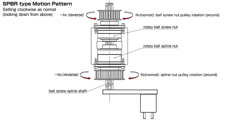
Motion Pattern:
Motion |
Input |
Output |
||||
Ball screw nut |
Spline nut |
Direction | Travel distance (linear) |
Revolution (rotional) |
||
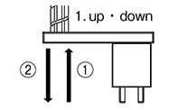 |
N1 (normal) |
0 |
1 |
L= N1.R (up) |
0 |
|
-N1 (reverse) |
0 |
2 |
L= -N1.R (down) |
0 |
||
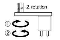 |
N1= N2 |
1 |
0 |
N2 (normal) |
||
-N1= -N2 |
2 |
0 |
-N2 (reverse) |
|||
 |
0 |
1 |
L= N2.R (down) |
N2 (normal) |
||
0 |
2 |
L= -N2.R (up) |
-N2 (reverse) |
|||
N1 -N1 |
N2 (normal) |
1 |
L=(N2-(±N1)).R |
If N2-(±N1)>0 |
N2 (normal) |
|
4 |
If N2-(±N1)<0 (up) |
|||||
-N2 (reverse) |
3 |
L=(-N2-(±N1)).R |
If -N2-(±N1)>0 (down) |
-N2 (reverse) |
||
2 |
If -N2-(±N1)<0 (up) |
|||||
| L = travel distance (mm), R = ball screw lead N1 = number of ball screw nut rotations, N2= number of ball spline nut rotations |
||||||