ALUMINIUM MOTION GUIDANCE
- LOADS, MOMENTS and PARALLELISM
Loads:
Max speed: 2m/s
Max acceleration: 30m/s2
Max temperature: 60ºC
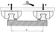
Torsional Moments:
Torsional Moments can be converted into an equivalent applied load (in Newtons) using the following calculation:
Fv1 = Mt
where Mt is the torsional moment in Nmm and a is the distance between the rails in mm.
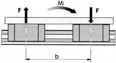
Longitudinal Moments:
Longitudinal Moments can be converted in a similar manner using the distance between the carriages along the rail:
Fv2 = Ml / b
where Ml is the longitudinal moment in Nmm and b is the distance between the carriages on the same rail (mm).
Selection of Size:
To determine the size required, use the following calculation for P:
P must not exceed the P max for the given size:
| Size | Pmax (N) |
|---|---|
| 15 | 750 |
| 20 | 1700 |
| 25 | 2500 |
P = kf . (Fv + Fh + t . Mt + s . Ml)
where kf is the operating factor (see table), Fv is the total vertical load (including Fv1 and Fv2 from above) and Fh is the total horizontal load. Factors Mt and Ml only come into effect if only one carriage and one guide rail is used - their constants t and s are listed below. For all other applications, the moments should be converted into equivalent vertical loads (Fv1 and Fv2) using the calculations above.
Recommended Operating Factor (kf):
| Factor kf | Application |
|---|---|
| 1.0 | Linear motion guide with manual drive |
| 1.2 | Linear motion axis with ball screw |
| 1.5 | Linear motion axis with toothed belt drive |
| 2.0 | Axis of machine tool not subjected to dirt |
| 7.0 | Linear motion axis with linear motion drive |
| 8.0 | Linear motion axis with pneumatic drive |
Moment Constants, t and s:
| Size | t | s |
|---|---|---|
| 15 | 140 | 180 |
| 20 | 110 | 120 |
| 25 | 100 | 110 |
Maximum service life is 4000 km for a standard block with initial greasing. This can be extended to 12500 km by use of two lube units. If the lube units are relubricated after 12500 km, then a life of 25000 km can be expected.
Nominal Life:
This can be calculated using either of the following equations:
L = (C / F)3 , where L is nominal life in km, C is dynamic load capacity (N) and F is the equivalent load (N)
or
Lh = L / (2.s.n.60) , where Lh is nominal life in hours, s is the length of stroke (m) and n is the repetition rate (complete cycles per minute)
Parallelism:
The system should be aligned in the following 3 directions in order to ensure the travel life is not reduced.
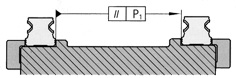
The following table shows the tolerance (mm) for dimension P when aligning the rails.
| Size | Normal | Preloaded |
|---|---|---|
| 15 | 0.020 | 0.008 |
| 20 | 0.026 | 0.010 |
| 25 | 0.031 | 0.014 |
Height Alignment (lateral):
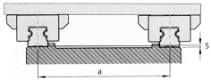
The permissible vertical offset, S (mm), is given by S = a f , where a is the distance between the guide rails and f is the calculation factor (see below).
| Calculation Factor | Normal | Preloaded |
|---|---|---|
| f | 0.0012 | 0.00035 |
Height Alignment (longitudinal):
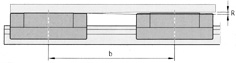
The permissible offset along the rail is given by R = b g , where b is the distance between the carriages (see left) and g is the calculation factor (see below).
| Calculation Factor | Normal | Preloaded |
|---|---|---|
| g | 0.0006 | 0.00021 |
Related Products and Links