


HOME > LINEAR BEARINGS > BALL BUSHINGS > REVERSE FLANGED BALL BUSHINGS
REVERSE FLANGED BALL BUSHINGS:
PDF Catalogue of Linear Bearings
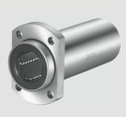 |
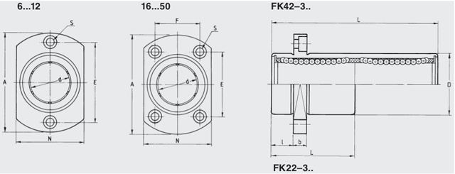
This special flanged ball bushing allows reverse mounting, on which the shorter part of the bushing is inserted into the housing bore and the longer part is protruding. The flange is cut away on the sides to reduce the space required. Available in standard length and tandem length. The Reversed-Flange Ball Bushings are available with two seals and a plastic ball retainer as FK22-3.. (standard length) and as FK42-3.. (tandem length). If required the ball bushing is available unsealed as FK20-3.. and FK40-3.. |
Part Number |
Part Number |
d | D | L | b | I | A | N | E | F | S | Load C (N) |
Load C0(N) |
Weight (kg) |
.stp File |
| Standard | Tandem | ||||||||||||||
| FK22-306 | 6 | 12 | 19 | 5 | 5 | 28 | 18 | 20 | M3 | 206 | 265 | 0.02 | |||
| FK42-306 | 6 | 12 | 35 | 5 | 5 | 28 | 18 | 20 | M3 | 323 | 530 | 0.03 | |||
| FK22-308 | 8 | 15 | 24 | 5 | 5 | 32 | 21 | 24 | M3 | 280 | 400 | 0.03 | |||
| FK42-308 | 8 | 15 | 45 | 5 | 5 | 32 | 21 | 24 | M3 | 440 | 800 | 0.05 | |||
| FK22-310 | 10 | 19 | 29 | 6 | 6 | 40 | 25 | 29 | M4 | 372 | 549 | 0.06 | |||
| FK42-310 | 10 | 19 | 55 | 6 | 6 | 40 | 25 | 29 | M4 | 588 | 1100 | 0.09 | |||
| FK22-312 | 12 | 21 | 30 | 6 | 6 | 42 | 27 | 32 | M4 | 520 | 800 | 0.07 | |||
| FK42-312 | 12 | 21 | 57 | 6 | 6 | 42 | 27 | 32 | M4 | 830 | 1600 | 0.10 | |||
| FK22-316 | 16 | 28 | 37 | 6 | 6 | 48 | 34 | 31 | 22 | M4 | 790 | 1200 | 0.11 | ||
| FK42-316 | 16 | 28 | 70 | 6 | 6 | 48 | 34 | 31 | 22 | M4 | 1250 | 2400 | 0.18 | ||
| FK22-320 | 20 | 32 | 42 | 8 | 8 | 54 | 38 | 36 | 24 | M5 | 900 | 1400 | 0.17 | ||
| FK42-320 | 20 | 32 | 80 | 8 | 8 | 54 | 38 | 36 | 24 | M5 | 1430 | 2800 | 0.25 | ||
| FK22-325 | 25 | 40 | 59 | 8 | 8 | 62 | 46 | 40 | 32 | M5 | 1000 | 1600 | 0.33 | ||
| FK42-325 | 25 | 40 | 112 | 8 | 8 | 62 | 46 | 40 | 32 | M5 | 1590 | 3200 | 0.53 | ||
| FK22-330 | 30 | 45 | 64 | 10 | 10 | 74 | 51 | 49 | 35 | M6 | 1600 | 2800 | 0.39 | ||
| FK42-330 | 30 | 45 | 123 | 10 | 10 | 74 | 51 | 49 | 35 | M6 | 2540 | 5600 | 0.65 | ||
| FK22-340 | 40 | 60 | 80 | 13 | 13 | 96 | 96* | 55.1 | 55.1 | M8 | 2200 | 4100 | 1.06 | ||
| FK42-340 | 40 | 60 | 151 | 13 | 13 | 96 | 96* | 55.1 | 55.1 | M8 | 3500 | 8200 | 1.57 | ||
| FK22-350 | 50 | 80 | 100 | 13 | 13 | 116 | 116* | 69.3 | 69.3 | M8 | 3900 | 8100 | 2.20 | ||
| FK42-350 | 50 | 80 | 191 | 13 | 13 | 116 | 116* | 69.3 | 69.3 | M8 | 6200 | 16200 | 3.60 |
* N.B. Sizes 40 and 50 do not have a cut away flange